| Outline: |
| Kirchoff's Current Law |
| Kirchoff's Voltage Law |
| Ohm's Law |
| Independent Sources |
| Reducing Circuits |
| Voltage Division |
| Current Division |
Kirchoff's Current Law
Kirchoff's Current Law (KCL) states:
The Sum of the currents entering a node is always zero.
Or we can say the sum of the currents entering a node = sum of currents leaving the same node.
The Sum of the currents entering a node is always zero.
Or we can say the sum of the currents entering a node = sum of currents leaving the same node.
Before elaborating on this law, let's first define what a node is:
A node is a connection point of two or more elements.
The table below shows some circuits and their nodes:
| This circuit has four nodes: | 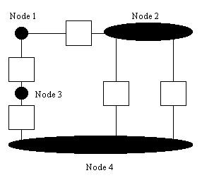 |
| This circuit has six nodes: | 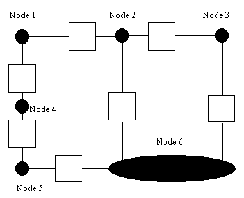 |
| This circuit has three nodes: | 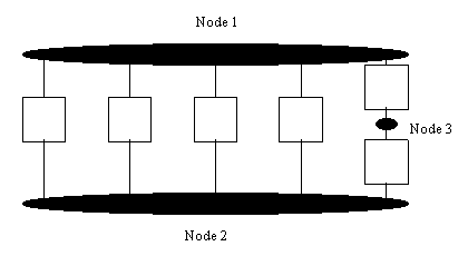 |
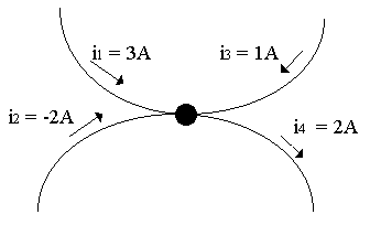
Σientering = Σileaving
| In this subcircuit, we have one node shown. At this node we have three currents entering the node and one current leaving the node. Applying KCL: i1 + i2 + i3 = i4 3 + -2 + 1 = 2 2 = 2 thus KCL holds true. |
 |
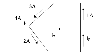
| In this subcircuit, we will use KCL to find iy Appying KCL at the left node: 3A + 4A = 2A + ix ix = 5A Now applying KCL at the right node: ix + iy = 1A 5A + iy = 1A iy = -4A |
 |
Σientering = Σileaving
OR
Σientering - Σileaving = 0
OR
- Σientering + Σileaving = 0
Top of Page
Kirchoff's Voltage Law
Kirchoff's Voltage Law (KVL) states:
The Sum of the voltage drops equals the sum of the voltage rises around any closed path.
The Sum of the voltage drops equals the sum of the voltage rises around any closed path.
ΣVdrops = ΣVrisesOR
ΣVdrops - ΣVrises = 0
Now lets apply KVL in the following problems:
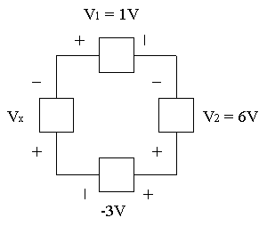
| In this circuit, we have one closed path. Typically we refer to a closed path as a loop. In this problem we will find Vx using KVL. Starting at the top-left corner and going clockwise we apply KVL: V1 - V2 + (-3V) + Vx = 0 1V - 6V + -3V + Vx = 0 -8V = -Vx Vx = 8V |
 |
| In this circuit, we will use KVL to find Vx, Vy, & Vz Note: We will also write KVL assuming a clockwise direction. The right most loop has only one unknown, so we will apply KVL there first: +3V - 9V - (-2V) + Vx = 0 -4V + Vx = 0 Vx = 4V Now applying KVL at the middle and left-most loops: -Vx + Vy = 0 Vx = Vy = 4V -Vy - Vz = 0 -Vy = Vz = -4V |
 |
Top of Page
Ohm's Law
Before defining Ohm's Law, let's elaborate on what a resistor is:
A resistor is a circuit element which is neither an insulator or conductor.
Current can pass through a resistor, however there is some resistance.
A resistor resists the flow of current. This resistance means that
some work must be done to "push" current through the resistor. Whenever
work is done on charge, we have voltage. Thus, when current flows
through a resistor, there is some voltage across the resistor.
The symbol for the resistor is:

The unit for resistance is ohms and the symbol is:
Ω
The voltage across a resistor is proportional to the current flowing in the resistor.
The larger the current in the resistor the larger the voltage across the resistor.
The resistance of the resistor is the constant of proportionlality.
So Ohm's Law is:
V = IR
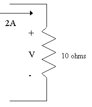
| In this problem we will find V using Ohm's Law: V = IR V = 2A(10 ohms) = 20 Volts |
 |
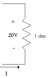
| Note here that current is going into the negative side of the resistor: Note: Current can only flow from a higher voltage potential to a lower voltage potential (like water flowing down stream), Therefore in this problem you must use this form of Ohm's Law: Now find I: Since V = -IR in this problem then I = -V/R I = -(20 V)/(1 ohm) I = -20 Amps |
 |
Summary:
Use V = IR if current is shown flowing into the positive side of the resistor, and
use V = - IR if the current is shown flowing into the negative side of the resistor.
Use V = IR if current is shown flowing into the positive side of the resistor, and
use V = - IR if the current is shown flowing into the negative side of the resistor.
Top of Page
Independent Sources
In order to build a useful circuit, there needs to be a power source.
Without a power source or Voltage, current will not flow.
What is an independent source?
An independent source supplies a fixed voltage or current, independent of
anything else.
Below are two independent soureces:
| These are independent voltage sources. The first is a power supply that provides a constant voltage. The second is a battery that also provides a constant voltage. |
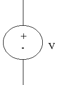 |
 |
| These is an independent current sources. Independent current sources are rare in the real world so consider this to be a theoretical device. You will see later that a current source can be constructed from a voltage source. |
 |
 |
When doing circuit analysis in this course,
always
assume the voltage across the voltage source is FIXED at the value specified.
Also always assume the current through the current source is FIXED at the value specified.
That's why we call these independent sources!!!
Where are we now?
With Kirchoff's Laws and Ohm's Law we can analyze any circuit.
Every other concept in this course is based on these principles.
Congratulations on getting this far!
Study Problems
After clicking on the following link enter 1-1 for the problem and 1 for the step:
Study Problem 1-1
After clicking on the following link enter 1-2 for the problem and 1 for the step:
Study Problem 1-2
After clicking on the following link enter 1-3 for the problem and 1 for the step:
Study Problem 1-3
After clicking on the following link enter 1-4 for the problem and 1 for the step:
Study Problem 1-4
Top of Page
Reducing Circuits
When analyzing a circuit, it is often easier to do so if the circuit can be simplified
or reduced. In this section we will consider how a colletion of resistor can be
reduced down to fewer resitors.
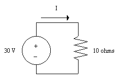
Consider the following two circuits:| Write a KVL equation for this circuit. Recall that V10=IR Start at the bottom left corner and go clockwise: -30V + 10I = 0 30 = 10I |
 |
| Write a KVL equation for this circuit. Recall that V5=IR Start at the bottom left corner and go clockwise: -30V + 5I + 5I = 0 -30V + 10I = 0 30 = 10I |
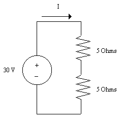 |
| Both circuits are described by the same equation, therefore they are electrically the same circuit. This means that you can replace one circuit with the other. We can simplify the second circuit by replacing it with the first circuit. |
|
When performing circuit analysis, if two circuits generate the same mathematical
equations,
then we say the two circuits are equivalent.
Series Resistors:
Consider the following two circuits:| Write a KVL equation for this circuit. -V + R1I + R2I + R3I = 0 -V + I(R1 + R2 + R3) = 0 -V + IReqv = 0 where Reqv = R1 + R2 + R3 |
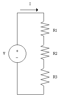 |
| Since Reqv = R1 + R2 + R3 then we can replace the three resistors with one resistor. |
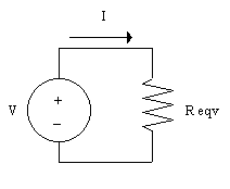 |
| Resistors which carry the same current are in series. In this case R1, R2, and R3 are all in series. They all carry current I Resistors in series can be added and then replaced with one resistor equivalent to to their sum. ΣRi = Reqv |
|
Study Problem
After clicking on the following link enter 1-5 for the problem and 1 for the step:
Study Problem 1-5
Parallel Resistors:
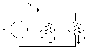
Consider the following two circuits:| In this circuit R1 and R2 are said to be in parallel because they have the same two terminal nodes, therefore they have to have the same volrage across them. V1 = VS and V2 = VS Using Ohm's Law we know that I=V/R Therefore: I1 = VS/R1 and I2 = VS/R2 Applying KCL at the top node we generate the following equation: IS = I1 + I2 IS = VS/R1 + VS/R2 Factoring out VS we get: IS = VS(1/R1 + 1/R2) Now let's obtain the resistance which is equivalent to the two resistors in parallel: Recall that VS/IS = Requivalent and IS/VS = 1/Requivalent 1/Requivalent = IS/VS = 1/R1 + 1/R2 1/Requivalent = (R2 + R1)/{R1*R2) Threrefore two resistors in parallel can be reduced with the following expression: Requivalent = {R1*R2)/(R1 + R2) |
 |
Using this information we will reduce the following circuits:
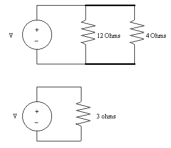
| The two circuits shown here are equivalent: Req. = {R1*R2)/(R1 + R2) Req. = {12*4)/(12 + 4) = 48/16 = 3 Ohms Req. = 3 Ohms |
 |
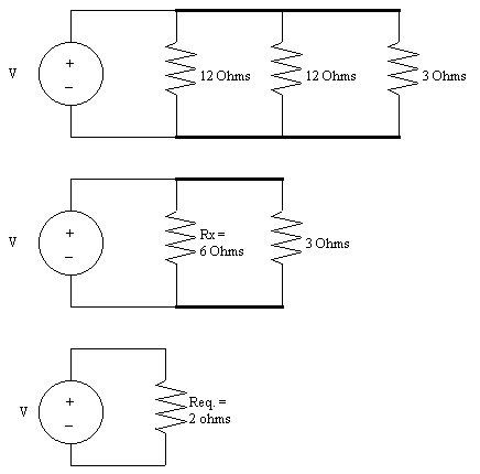
| The three circuits shown here are also equivalent: Rx = {R1*R2)/(R1 + R2) Rx = {12*12)/(12 + 12) = 144/24 = 6 Ohms Req. = {R3*Rx)/(R3 + Rx) Req. = (3*6)/(3+6) = 18/9 = 2 Ohms |
 |
Combining Resistors in Parallel:
If we always combine resistors in parallel "two-at-a-time"then we can use the equation: Requivalent = {R1*R2)/(R1 + R2) Otherwise we must use the more general form for 'n' resistors: 1/Requivalent = 1/R1 + 1/R2 + .... + 1/Rn |
|
Study Problem
After clicking on the following link enter 1-6 for the problem and 1 for the step:
Study Problem 1-6
Top of Page
Voltage Division
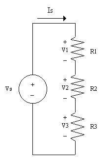
Now let's return to a series circuit:
| Continuing with analysis: Req. = R1 + R2 + R3 IS = VS/Req. V1 = IS * R1 V2 = IS * R2 V3 = IS * R3 Now plug in IS: V1 = (VS/Req.) * R1 = (R1/Req.)*VS V2 = (VS/Req.) * R2 = (R2/Req.)*VS V3 = (VS/Req.) * R3 = (R3/Req.)*VS In plain english what do these mathematical equations say? The voltage across a series resistor is some percentage of the total voltage, VS This percentage is equal to the individual resistor's resistance divided by the equivalent resistance, Req. The voltage is being divided among the series resistors, hence this is called Voltage Division |
 |
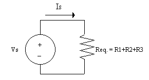 |
With the circuit above does KVL still hold true? |
||
Study Problem
After clicking on the following link enter 1-10 for the problem and 1 for the step:
Study Problem 1-10
Top of Page
Current Division
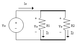
Now let's return to a parallel circuit:
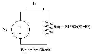
| Continuing with analysis: From the circuit on the left we know that I1 = Vs/R1 and I2 = Vs/R2 From the reduced circuit on the right we know that Vs = Is*Req. Now we will plug the second equation into the first equation: I1 = (Is*Req.)/R1 I2 = (Is*Req.)/R2 From the section on parallel resistors we know: Req. = R1*R2/(R1+R2) If we plug this into the last set of equations we get: I1 = (Is*[R1*R2/(R1+R2)])/R1 I2 = (Is*[R1*R2/(R1+R2)])/R2 Note that R1 factors out of the first equation and R2 factors out the the second equation giving the following: I1 = Is*[R2/(R1+R2)] I2 = Is*[R1/(R1+R2)] |
 |
 |
|
In plain english what do these mathematical equations say? The current through a parallel resistor is some percentage of the total source current, IS This percentage is equal to the OTHER resistor's resistance divided by the sum of the two resistors, R1 and R2 The currrent is being divided among the parallel resistors, hence this is called Current Division |
||
The equations get much more complicated if you work with three or more resistors. |
||
Study Problem
After clicking on the following link enter 1-11 for the problem and 1 for the step:
Study Problem 1-11
Top of Page